
Trying to find sound examples of this was difficult so I took the time to do the research and perform tests so you will have the real data and an example.
Using the ADC (Analog to Digital Converter) in the ATmega32U4 is simpler than the Atmel documentation seems. I found many errors in Atmel’s documentation so let me clear up some of the misconceptions
Why measure VCC?
Measuring VCC might be necessary if your Arduino project runs on battery, primarily, or as a backup power source. The advantage of measuring VCC internally is that doing so will not require using a pin on the Micro. The micro has a dedicated channel for making this measurement.
Programmer’s view of the ADC
The ATmega32U4 ADC can be controlled by the use of five 8-bit registers. The ADC is capable of making single-ended or differential measurements. For our purposes, we will discuss only single-ended measurement.
For more detail refer to Atmel’s documentation for ATmega32U4.
ADMUX – Multiplexer Selection Register
- Reference selection (AREF, VCC or 2.56V).
- Contains 5 of the 6 MUX bits used to select the channel to be measured.
- One bit is used to justify, left or right, the measurement results in the ADC’s output registers.

ADCSRA – ADC Control and Status Register A
- Enable and trigger the ADC.
- Sets the conversion clocking frequency of the prescaler.
- Enables interrupt when a conversion is complete.
For the Micro, this register is initialized differently than the ATmega32U4 default. The ADC is enabled and the division factor for the prescaler is set to 128. The 16MHz clock speed is divided by 128 so ADC conversion runs at 125 KHz.

ADCSRB – ADC Control and Status Register B
- High Speed Mode selection bit.
- The sixth MUX selection bit.
- Auto Trigger source selection.
The Atmel ATmega32U4 datasheet incorrectly indicates that MUX5 and ADTS3 are read-only.

DIDR0 and DIDR2 – Digital Input Disable registers
Setting a bit to ‘1’ will disable the corresponding data input buffer. It is advised to disable the respective digital input buffer when using a pin for analog input in order to reduce power consumption by the digital input buffer.


ADCL and ADCH – Output registers
Conversion results are stored in registers ADCH and ADCL. Arduino code can access the registers as a single unsigned 16-bit value using ADCW.
ADLAR = 0 (Default)
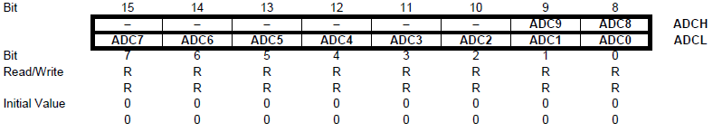
ADLAR = 1


ATmega32U4 ADC Block Diagram
Measuring VCC
To take full advantage of battery monitoring and brownout detection one must consider the specifications of the Micro’s onboard NCP1117-5 voltage regulator and ATmega32U4 microcontroller.
The ATmega32U4’s safe operating voltage range is 4.5 to 5.5 VDC for a clock frequency of 16 MHz. For an 8 MHz clock, the ATmega32U4 can operate down to 2.7 VDC.
The Micro employs an NCP1117-5, 5 volt, low dropout, voltage regulator. The 5 volt regulator will output 4.95 to 5.05 VDC with a supply voltage of about 6 VDC. The voltage regulator is turned on in a non-regulating mode, when USB is not connected to the Micro, and at least ~1 VDC is applied to its input. The regulator will begin regulating at its rated voltage when the input voltage is about 1 volt higher than its rated output voltage. In other words, the regulator will regulate until the input voltage falls below about 6 volts at which point it will stop regulating (drop out) and allow power output to sag down to about 1 volt before there is not enough voltage to support the regulator. In my experiments, I’ve been able to lower VCC to 2.67 VDC and the Micro continued to function.
AVCC is connected to VCC in the Micro so AVCC and VCC are the same voltage and the use of the references is just symantec.
When powering the Micro from the DC power connector, use a power supply or battery with an output of 6.5 to 18 VDC. That will ensure a solid 4.95 to 5.05 VDC output of the regulator, meeting any current requirement of the Micro. The onboard regulator will permit operation below the expected input range so monitoring AVCC can allow your project detect this condition and produce an alarm or enter a safe mode of operation under an imminent power failure condition. This is referred to as brownout detection.
We cannot use Arduino ADC functions to configure the ADC to read the AVCC voltage for two reasons. Firstly, the ArduinoCore_avr library does not have the defines for the analogRead function to access the AVCC analog channel. Secondly, the analogReference function does not configure the ADC’s analog reference but rather saves the reference for configuration during the analogRead function. This is to prevent inadvertently shorting out the Micro if something is connected to AREF when AVCC is selected. Therefore, we must manually configure the ADC in code.
I used the following sketch to test when the Micro stopped functioning as I slowly decreased VCC. The Micro continued to function until the voltage dropped below 2.67 VDC. I used a switchable USB hub that allowed me to remove USB power after programming the Micro but continue the Serial Monitor USB connection. The Arduino IDE Serial Monitor was used to monitor the “I’m alive!” report.
void setup() {
  pinMode(LED_BUILTIN, OUTPUT);

  Serial.begin(9600);
  while (!Serial);
  Serial.println("Begin.");
}

void loop() {
  Serial.println("I'm alive!");

  digitalWrite(LED_BUILTIN, HIGH);
  delay(1000);
  digitalWrite(LED_BUILTIN, LOW);
  delay(1000);
}
Normally, the selected channel is an arbitrary voltage to be measured against a fixed VREF. But when measuring AVCC, the ADC is configured in the opposite manner. AVCC is the arbitrary voltage and is connected to VREF while the fixed 1.1 volt internal reference is selected as the analog input. The implication is that the measured result in ADCW is actually a factor rather than a proportion in the measurement.
The ADC will use the DAC (Digital-to-Analog-Converter) to produce a voltage within the range of the VREF voltage. Over 13 ADC clock cycles, the ADC will successively approximate the DAC voltage until it arrives at the closest DAC output voltage to the channel being measured. The 10-bit binary value controlling the DAC is then clocked into the ADCH and ADCL registers.
When measuring AVCC, the DAC uses AVCC as the reference voltage but measures the 1.1 volt Bandgap reference. The lower AVCC drops, the higher the DAC value needed to produce 1.1 VDC.
We calculate VCC in this way:
unsigned int result = (1100L * 1023L) / ADCW;
This code will measure the 1.1 VDC Bandgap reference against AVCC and report the approximate value to the Serial Monitor.
unsigned vcc;

void setup() {
  // initialize digital pin LED_BUILTIN as an output.
  pinMode(LED_BUILTIN, OUTPUT);

  // Set ADMUX to read 1.1V Bandgap reference against AVcc which
  // is tied to VCC on the Micro. Normally we should wait for Vref
  // to
 settle. It only takes about 4 microseconds but it's a good
  // practice to wait 1 millisecond when switching AREF. We don't
  // need to specify settling time in this case because we'll use
  // that time doing other things. Also, since we're not measuring
  // a
 pin, there's no need to use the DIDR register.
  ADMUX = _BV(REFS0) | _BV(MUX4) | _BV(MUX3) | _BV(MUX2) | _BV(MUX1);
  ADCSRB = 0;

  Serial.begin(9600);
  while (!Serial);
  Serial.println("Begin.");
}

void loop() {
  vcc = readVcc();

  // readVcc returns the approximate voltage of VCC in millivolts.
  // We'll
 convert that value to volts and send it to the Serial
  // Monitor.
  Serial.print("Vcc (V): ");
  Serial.println(String((float)vcc/1000.0, 3));

  // Just to slow things down a bit.
  digitalWrite(LED_BUILTIN, HIGH);
  delay(1000);

  digitalWrite(LED_BUILTIN, LOW);
  delay(1000);
}

unsigned int readVcc() {
  unsigned int result;

  // Trigger a conversion. The ADSC bit will return to LOW after
  // conversion is complete.
  ADCSRA |= _BV(ADSC);
  while (bit_is_set(ADCSRA,ADSC));

  // The result is stored in the combination of the ADCH and ADCL
  // registers. They can be accessed together using ADCW. ADCW is
  // an
 unsigned int. The lowest value read as 0, and the highest
  // value
 read is 2n-1 (1023). We must calculate the actual value
  // read.
  result = (1100L * 1023L) / ADCW;
  return result;
}